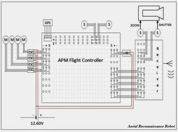
Figure 4.3 Schematic Diagram of Aerial Reconnaissance Robot
Figure 4.3 presents the schematic diagram of aerial reconnaissance robot’s main circuit. The APM is the central component of the system. The receiver manages the signal coming from the route controller, then it feeds the signal to the APM, then the APM controls the servo for the camera, to be able to control the motor the APM feeds the signal to the ESC, the ESC controls the motor for steady flight.
0 comments:
Post a Comment