Showing posts with label System Design and Circuit Analysis. Show all posts

Thursday, June 5, 2014

Controlling the Quad Copter

Controlling the Quad Copter

Figure 4.4 Controlling Quad copter
When a rotors turn, it has to overcome air resistance. The reactive force of the air against the rotor causes a reactive moment called the “Induced moment”. The induced moment acts on the rotor in the direction opposite to the rotation of the rotor.

As everyone knows, conventional helicopter require the tail-rotor to counteract the induced moment, in the hover both sets of diagonal rotors turn in opposite directions (as indicated by the opposite direction of the arrows in Fig.)

As long as all rotors experience the same induced moment which is mostly a function of speed of rotation and rotor blade pitch the sum of all induced moments is zero and there is no horizontal rotation. If one set of rotors, for example the one that turns counter-clockwise in fig., increase their rotational speed or their pitch, the resultant net induced moment will cause the quad copter to rotate clockwise.

It is important to note that because of the diagonal arrangement, this operation has no effect on translation in x or y direction. The effect on up/down motion can be compensated by reducing the pitch speed of the other diagonal pair, although in practice this is not quite so easy without some sort of feedback control.
Monday, June 2, 2014

Schematic Diagram of Aerial Reconnaissance Robot

Schematic Diagram of Aerial Reconnaissance Robot

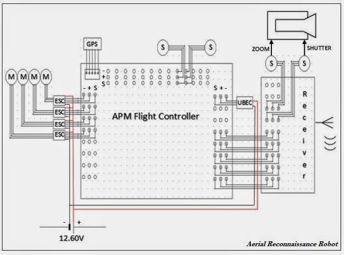
Figure 4.3 Schematic Diagram of Aerial Reconnaissance Robot

     Figure 4.3 presents the schematic diagram of aerial reconnaissance robot’s main circuit. The APM is the central component of the system. The receiver manages the signal coming from the route controller, then it feeds the signal to the APM, then the APM controls the servo for the camera, to be able to control the motor the APM feeds the signal to the ESC, the ESC controls the motor for steady flight.

System Flowchart

System Flowchart

System Flowchart

System Flowchart

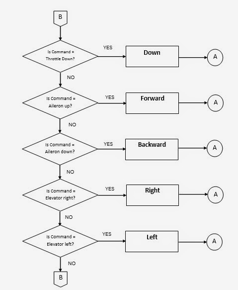
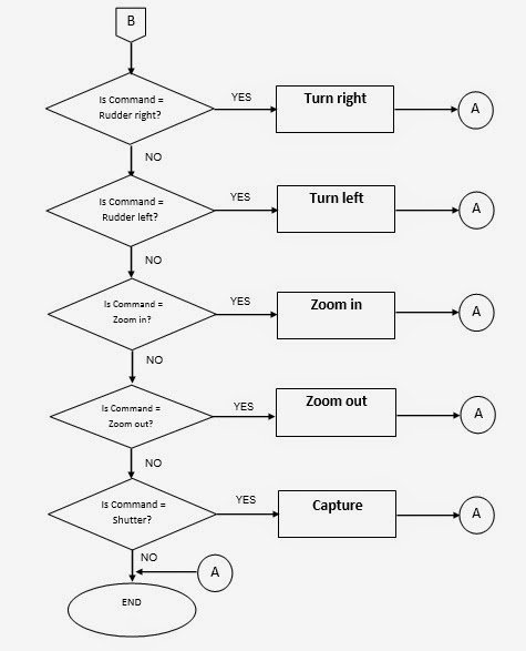
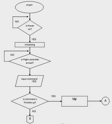
Figure 4.2 The System Flowchart

     Figure 4.2 indicates what will be the movement of the quad copter once the input command initialize. The flight controller tells which motor will increase the power that will create movement of the quad copter. The motor will response either left, right, rotate left, rotate right, up, down, forward and backward. The output will be dependent on the RF controller. The expected movement of the quad copter and camera will be executing once the signal was sent. And once the signal was received by the RF controller, the program will analyze the receive data and it will automatically send the requested command to be performed.


Sunday, June 1, 2014

System Block Diagram

SYSTEM DESIGN AND CIRCUITS ANALYSIS

This chapter contains the system design, circuits, diagrams, discussion, computations and components.


System Block Diagram

     Fig. 4.1 shows the flow of the project from input to output. The transmitter board gives the command that will be received by the receiver board. The receiver board will give the received command to the APM flight controller, it will be read by the flight controller and it will distinguish where that command is for, if for the GPS, Camera gimbal or Electronic Speed Controller. If the command is for the DC motors the flight controller will send the command to the Electronic Speed Controller (ESC) to regulate the speed of the motors to make it move sideways, forward, backward and turn. If the command is for the Camera gimbal the APM will send it to Camera Gimbal that will make it to tilt and be balanced. The GPS feeds information, like coordinates and more to the APM flight controller.